This article aims to help you understand the laser scanning errors that you might encounter during extraction using PCS or any other software. This is not a complete guide to all existing errors, but we try to focus on common ones which you might already seen. These errors can be scanner type-specific or general ones. We try to show you our approach, and how to handle these during extractions! Let’s get into it!
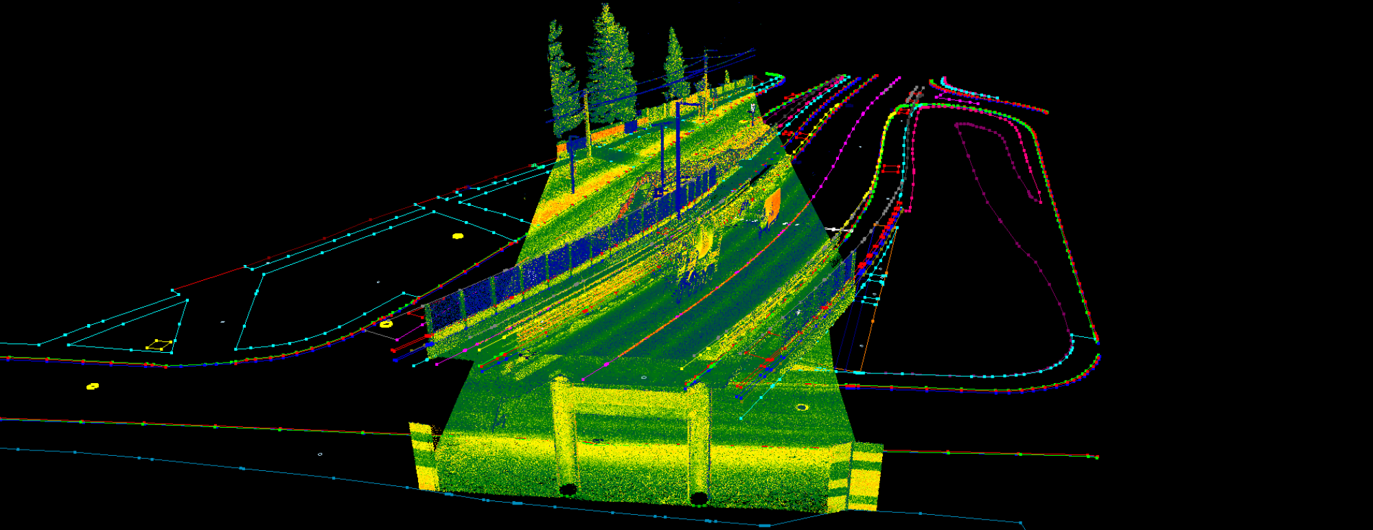
- Ghost Clouds
Also known as misalignment between clouds, ghosting, multipathing, registration error, overlapping scans or layering artefacts. This is the most common case, where the point cloud presents “multiple layers” from every object, like double walls or ground, poles, etc. As you can expect from the mentioned synonyms, it is a post-processing error, where the least squares adjustment – or similar mathematical process – does not provide sufficient results due to some uncertainties. We do not describe, what can be a reason behind this, we focus on how to handle these cases during extraction, as this is a common thing to do.
Ghosts can appear in all dimensions (XYZ), but in the Z dimension (vertical) ghosts are the most common. The difficult part here is to decide, which “layer” is accurate, as the ghost is a misalignment, where the adjustment couldn’t calculate the right values for the points based on the triangulation. We cannot know for sure, which is the right (accurate) layer. This error has a different source according to scanner types: for TLS it happens less, but for scanners without a 2-axis compensator this can happen at longer distances. For MLS scanners the GPS signal weakness can cause this. Slam scanners are quite sensitive distance-wise for this type of error, and also movement “imperfections”, loop errors or adjustments between projects/paths can be an origin.
The best solution is to re-process the data to eliminate this during the post-processing, but sometimes, it’s just not an option as you just received the LAS files, and that’s it. First, you need to inspect the specs of the project, what is the required accuracy. If the error is within the accuracy limit, you can pick one layer, usually the stronger one. The most common approach is to “take the middle”, so adjust the elevation to the middle of the layers, to minimize the error. If the data is coming from TLS, and you can turn off each scan station, you can try to find out, which station causes the error by turning it off one by one. It also may happen that, if you experience a thin layer of ghost, it is from a scan station, that is very far, and you experience a very thin layer of far points. This can be due to the lack of the 2-axis compensation, in these cases simply ignore these points. If the data is coming from MLS, and it is tiled, you can average the clouds, if this provides a sufficient result in terms of the project’s accuracy. If the misalignment happens in more than a few spots, like the whole cloud is misaligned, it is a clear sign that something went wrong during the post-processing (sometimes, this can fit to the project specs, if the extraction is 2D only). Averaging the layers is the most common solution here. If you receive the data in records (where the sides of the roads are in separate files), you can also try to find the “right” layer, by inspecting the cloud and turning on-off the records. Junctions and roundabouts are likely to get this type of error in MLS. If the data is coming from Slam, the situation is difficult, as the Slam post-processing provides fewer options for the users to adjust the data, especially between projects. We can recommend using the average solution, but it is also common that, if you experience only a thin layer of points, it’s coming from a further part of the trajectory, so these points can be ignored. If the data is coming from a UAV scan, the ghost effect might not be clearly visible, instead, you experience a thicker point cloud. The same rule applies here: try to set the elevation of the vectors to the middle of the cloud. Try to avoid zig-zag-like lines in the cloud in terms of elevation. If needed, set the vertexes by hand so you can maintain good quality.
Always crosscheck the method against the project specifications and consult with your supervisor, if you run into such an issue, as every company has a different policy handling these cases. Still, the best solution is to be prepared for the scanning, provide enough control points, and mitigate these errors during post-processing.
2. Water reflections and imperfections
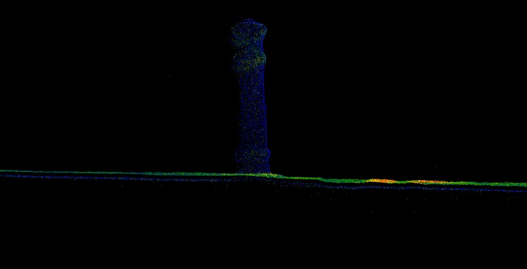
This error is tricky as if you do not pay attention, it can ruin your accuracy. The error does not affect all scanners in the same way. We mainly refer to Time of Flight (ToF) scanners, where the laser beam can be reflected or emitted by water. Scanners using the phase-shifting approach react differently to water, they are less vulnerable to this but still capable of generating this type of error.
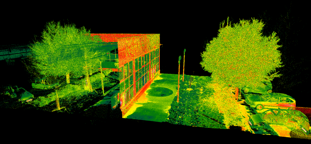
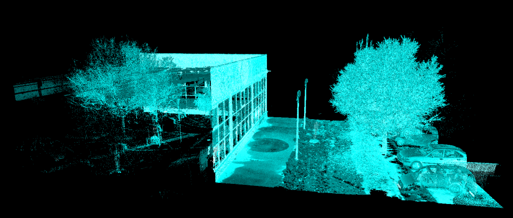
This type of error is prone to happen with higher-end scanners, where the scanner can record multiple points from a single laser shot. The reason behind this is the following: the laser shots once, and then the laser beam is reflected from the water (which can act as a mirror), and the shot returns to the scanner using the same path, but the reflection angle has not been taken into account, as the scanner cannot measure this “unexpected” angle, so the point will be created like the laser shot would be straight. The resulting points commonly have weaker intensities, which is the key factor in identifying the issue. In the above-shown images, the reflections are weaker (closer to the blue region of the colour scale). These points shall be ignored during the extraction. Always pay attention when you are using the drape tool to move down lines at the edge of a water body or around water spots in general, as the drape will also take into account the false points. It is recommended to crosscheck your lines to make sure the line is not snapped to a false point. The easiest way to identify the right spot is to search for the shift in intensity values, where the “colour” changes significantly.
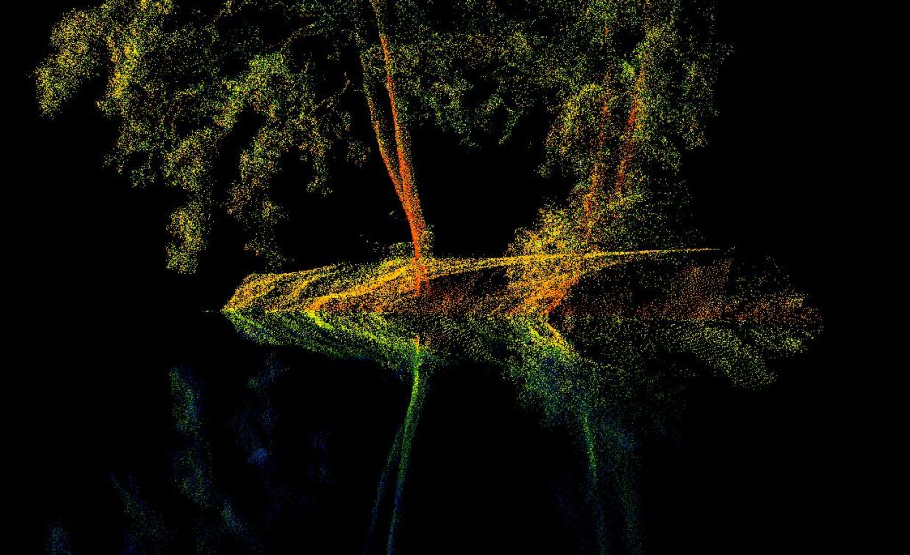
3. Glass reflections
This issue is slightly similar to the water reflections but with glass. In that way, the reflection can “copy” the street inside a building, or the inside of the building to the street.
This error can make life quite difficult in urban areas, around skyscrapers or malls, where huge glass surfaces are present. To make things worse, it is not as clear, what is a reflection and what is not, as the intensity is not as weak as the presence of water. This type of reflection can “fake” poles, signs and other objects. The best approach to mitigate these errors is to use the images with the point clouds, so it will be clear, what exists on site, and what is just a reflection. It is also recommended to mitigate these errors during post-processing, but commonly, you have no such option. Intensity can also indicate false points, RGB colours can also highlight this issue, but according to our approach, the best is to filter only the first returns from the laser data, as this type of error can happen only with scanners, which can record multiple returns from a single laser shot. Filtering to the first return can help identify the issued objects.
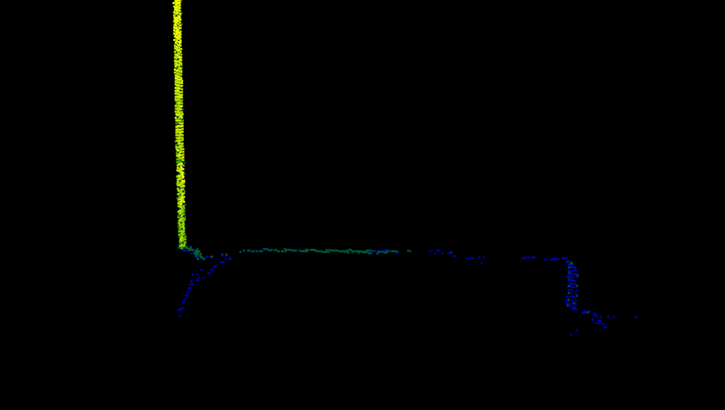
4. Edge overrun
This phenomenon can occur using TLS, MLS and Slam scanners. When a scanner’s laser beam reaches the edge of the back side of the kerb, sometimes the recorded point “overruns” the real location if the angle at which the shot touches the edge is too sharp. In that way, a thin layer of points is generated “as a slope” between the ground and the edge. These points are fake.
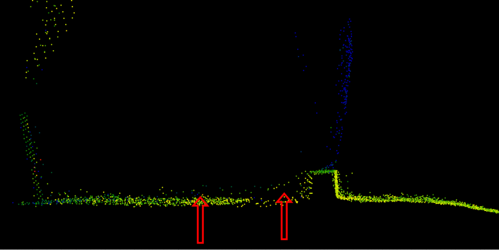
In the given example, the proper ground surface is visible, but this error can happen at the edge of the target area as well, and the user might not be aware that, these points are fake. We strongly recommend crosschecking the edges of the working area and do not trust points, which represent a slope behind a sharp edge. These points cannot be distinguished using intensity.
We hope this short guide helps you to better understand these phenomena, and help you to count on these during your extraction process. Our software toolkit has everything you need to handle these errors to ensure the highest quality for your products.
If you have a specific error which occurred during the use of PCS, and you would like to read about it here, feel free to comment on it!