We are continuously working on our software to make it more stable and implement new and exciting features. From now on, we will share updates with you, what has been changed, and what exciting features we are working on now. Let’s see the details…
- Easier survey data integration
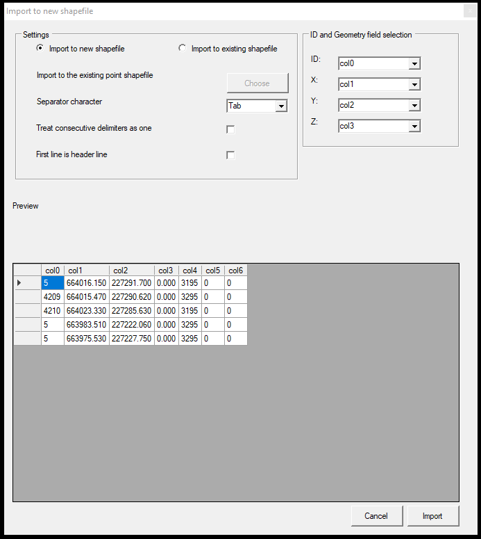
PCS is considered a bridge between the survey and GIS world, and as it is developed by surveyors, the functionality also favors the surveyor community. Now raw coordinate lists can be easily imported to PCS, to be used together with the point cloud data. The coordinate list can have multiple fields above the coordinates, like point code, PDOP, dx, dy, dz values, or comments, as you record in the total station and/or GNSS device. The imported points can be exported to DXF/DWG as well and can be kept in SHP to be uploaded to any database with their attributes.
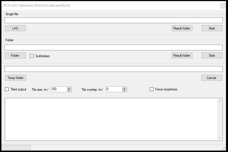
- Optimizer – Tiling functionality
The black-belt users are familiar with the PCS Optimizer stand-alone application, which can perform the necessary optimization in a separate thread using multiple CPU cores. Now, this tool has a tiling functionality, which means that, if you want to optimize a file or a folder, PCS will automatically take the file, and tile it to the required size to a separate folder. The user can define the tile size, like 50mx50m or 100mx100m. For the most convenient tiles, PCS will automatically align the tile corners with whole number coordinates.
- Point cloud density reduction to LAS file(s)
The tiling is a nice feature, but it’s possible you want to reduce the point density as well in a single tile or file. PCS can reduce the density of single or multiple LAS files in the project. For this, you can specify a cell size (voxel), which defines an x*x*x-sized cube, in which you can define, how much point you want to keep. This is not a simple 2D sub-sampling, this feature will keep equal point density on walls as well! Cool isn’t it?
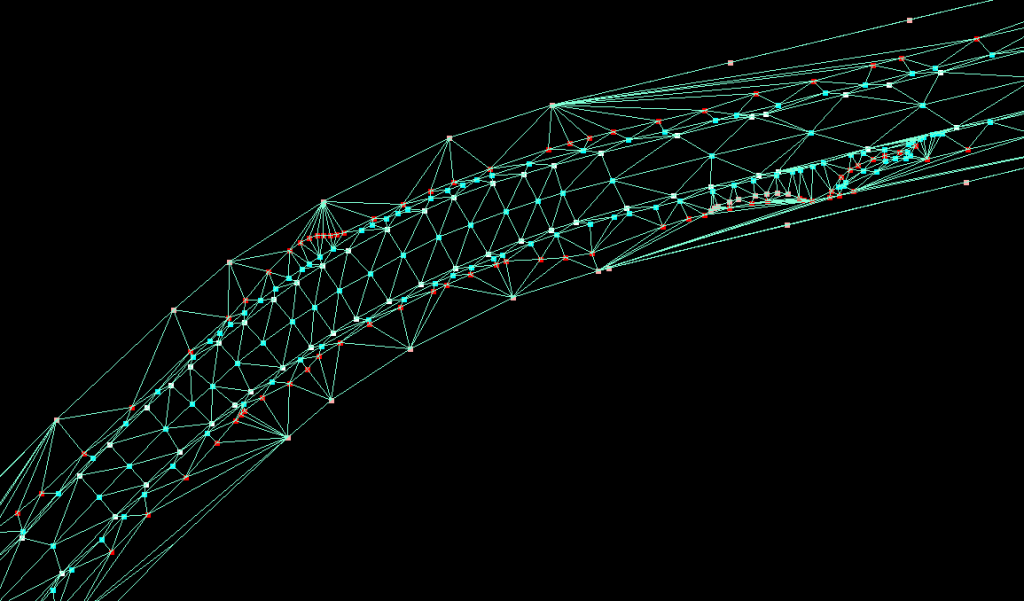
- Triangulator and surface upgrades
The Triangulator (or with a common name, TIN surface generator) is an old function in PCS, but it hasn’t got enough spotlight so far. Now we are about to put more focus on it. Originally, the triangulator was able to build a TIN surface based on clouds and vectors combined. Now, we allow it to use only topologically correct vectors as well, so you can build a pure vector-based surface. The triangulator output could be saved in polygon SHP before, but now, you can export it to DXF/DWG as 3D faces, so you can use it as a surface in Civil 3D as well! A dream come true for road designers with this function 🙂
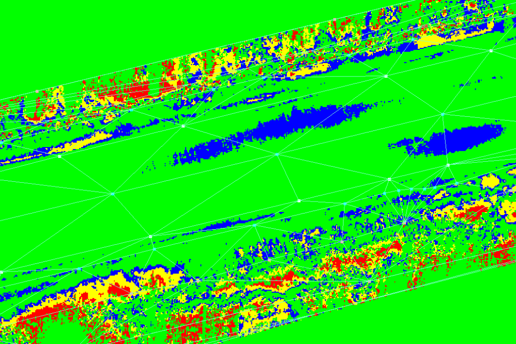
- Surface-point cloud elevation difference heatmap
For most companies, who are producing maps from point clouds, this is the biggest struggle: check if the vectors are aligned properly to the cloud. Of course, many software – such as PCS – have a drape function, which will drag a vertex to the point cloud based on criteria, but let’s be honest: drape cannot be trusted 100%. In some case, there is some noise, some false points, mirrored points from glass surfaces, water surface reflection, or the scanner you are using produce a unique-to-the-scanner error, which cannot be filtered out automatically. At the end of the day, someone from your company has to check the drawing, if all is good, and finding a few cm in a point cloud is a hard nut to crack. Until now!
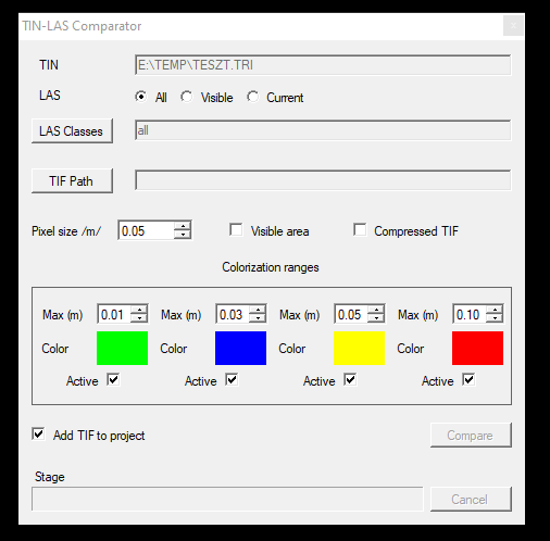
This function provides a major quality-of-life upgrade for our users! If you create (or import, but this will be described a little bit later) a TIN surface inside PCS, the software will inspect the distance between the point cloud and the surface and provides a georeferenced raster heatmap (with user-specified ranges) how well the surface aligns with the cloud. In that way, you can check the locations, where your surface does not align with the cloud, so you can fix only those locations. As the heatmap is georeferenced, you can use it in other environments like QGIS or AutoCAD!
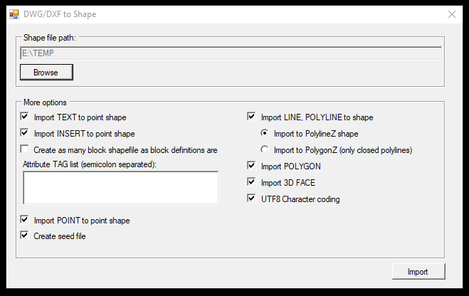
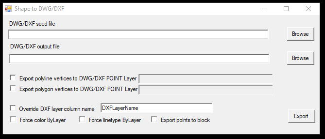
- DXF/DWG Import/Export upgrades
As PCS operates on an SHP basis, it is really important to pay attention to DXF/DWG questions, as a minimum of 50% of the PCS users use the vectors in a CAD environment.
The import of a DXF/DWG file to SHP now is able to properly handle 3D faces during import, which means that, you can have a TRI file (native PCS surface file) from a surface created for example in Civil 3D. This TRI file serves as a base for the surface-cloud distance calculation or for contour line generation.
During export, from SHP to DWG, multiple options become available. Now, you can override the DxfLayer with other attributes, if you need to use a different attribute for the DXF layer. Multiple attributes can be set to ByLayer from now on, like color or line type, and the automatic placement of the elevation value as block is in development, so if you need to deliver your 3D plans in 2D with elevations, there is a tool which can replace lisps or manual placement.
Above these updates, we are working on some really exciting things, which we will share with you in the next update, but we can promise that more and more CAD and point cloud manipulation tools will come in the upcoming months, and we are constantly working on to increase the software stability.
If you would like to know more about our tools, hit the comment section or write us an email!
Thanks for sharing